The Open Shortest Path First (OSPF) protocol is a link state protocol that handles routing for IP traffic. Its newest implementation, version 2, which is explained in RFC 2328, is an open standard. Open Shortest Path First (OSPF) is an open standard (not proprietary) and it will run on most routers independent of make. Open Shortest Path First (OSPF) uses the Shortest Path First (SPF) algorithm, developed by Dijkstra, to provide a loop-free topology. Open Shortest Path First (OSPF) provides fast convergence with triggered, incremental updates via Link State Advertisements (LSAs).
The main disadvantages of Open Shortest Path First (OSPF) are Open Shortest Path First (OSPF) requires more memory to hold the adjacency (list of OSPF neighbours), topology (a link state database containing all of the routers and their routes), and routing tables, Open Shortest Path First (OSPF) requires extra CPU processing to run the SPF algorithm and Open Shortest Path First (OSPF) is a complex routing protocol.
The two important concepts in case of OSPF are Autonomous Systems and Areas. Areas are used to provide hierarchical routing, within an Autonomous System. Areas are used to control when and how much routing information is shared across your network.
OSPF implements a two-layer hierarchy: the backbone (Area 0) and areas off of the backbone (Areas 1–65,535). Here the two different areas can summarize routing information between them. Route summarization helps to compact the routing tables. All areas should connect to Area 0 and all routers in an Area will have the same topology table.
The OSPF process builds and maintains three separate tables:
• A neighbour table – contains a list of all neighbouring routers.
• A topology table – contains a list of all possible routes to all known networks within an area.
• A routing table – contains the best route for each known network.
OSPF Neighbours
OSPF forms neighbour relationships, called adjacencies, with other routers in
the same Area by exchanging Hello packets to multicast address 224.0.0.5.
Only after an adjacency is formed can routers share routing information.
Each OSPF router is identified by a unique Router ID. The Router ID can
be determined in one of three ways:
• The Router ID can be manually specified.
• If not manually specified, the highest IP address configured on any
Loopback interface on the router will become the Router ID.
• If no loopback interface exists, the highest IP address configured on
any Physical interface will become the Router ID.
By default, Hello packets are sent out OSPF-enabled interfaces every 10
seconds for broadcast and point-to-point interfaces, and 30 seconds for nonbroadcast
and point-to-multipoint interfaces.
OSPF also has a Dead Interval, which indicates how long a router will wait
without hearing any hellos before announcing a neighbour as “down.” Default
for the Dead Interval is 40 seconds for broadcast and point-to-point
interfaces, and 120 seconds for non-broadcast and point-to-multipoint
interfaces. Notice that, by default, the dead interval timer is four times the
Hello interval.
OSPF routers will only become neighbours if the following parameters within
a Hello packet are identical on each router:
• Area ID
• Area Type (stub, NSSA, etc.)
• Prefix
• Subnet Mask
• Hello Interval
• Dead Interval
• Network Type (broadcast, point-to-point, etc.)
• Authentication
The Hello packets also serve as keepalives to allow routers to quickly
discover if a neighbour is down. Hello packets also contain a neighbour field
that lists the Router IDs of all neighbours the router is connected to.
OSPF Designated Routers
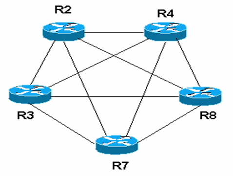
In multi-access networks such as Ethernet, there is the possibility of many neighbour relationships on the same physical segment. In the above example, four routers are connected into the same multi-access segment.
Using the following formula (where “n” is the number of routers):
n(n-1)/2 it is apparent that 6 separate adjacencies are needed for a fully meshed network. Increase the number of routers to five, and 10 separate adjacencies would be required. This leads to a considerable amount of unnecessary Link State Advertisement (LSA) traffic.
If a link off of Router A were to fail, it would flood this information to all
neighbours. Each neighbour, in turn, would then flood that same information to all other neighbours. This is a waste of bandwidth and processor load.
To prevent this, OSPF will elect a Designated Router (DR) for each multi-access
networks, accessed via multicast address 224.0.0.6. For redundancy
purposes, a Backup Designated Router (BDR) is also elected.
OSPF routers will form adjacencies with the DR and BDR. If a change
occurs to a link, the update is forwarded only to the DR, which then
forwards it to all other routers. This greatly reduces the flooding of LSAs.
DR and BDR elections are determined by a router’s OSPF priority, which
is configured on a per-interface basis (a router can have interfaces in
multiple multi-access networks). The router with the highest priority
becomes the DR; second highest becomes the BDR. If there is a tie in
priority, whichever router has the highest Router ID will become the DR.
OSPF Network Types
OSPF’s functionality is different across several different network topology
types.
Broadcast Multi-Access – indicates a topology where broadcast occurs.
• Examples include Ethernet, Token Ring, and ATM.
• OSPF will elect DRs and BDRs.
• Traffic to DRs and BDRs is multicast to 224.0.0.6. Traffic from
DRs and BDRs to other routers is multicast to 224.0.0.5.
• Neighbours do not need to be manually specified.
Point-to-Point – indicates a topology where two routers are directly
connected.
• An example would be a point-to-point T1.
• OSPF will not elect DRs and BDRs.
• All OSPF traffic is multicast to 224.0.0.5.
• Neighbours do not need to be manually specified.
Point-to-Multipoint – indicates a topology where one interface can connect
to multiple destinations. Each connection between a source and destination
is treated as a point-to-point link.
• An example would be Point-to-Multipoint Frame Relay.
• OSPF will not elect DRs and BDRs.
• All OSPF traffic is multicast to 224.0.0.5.
• Neighbours do not need to be manually specified.
Non-broadcast Multi-access Network (NBMA) – indicates a topology
where one interface can connect to multiple destinations; however,
broadcasts cannot be sent across a NBMA network.
• An example would be Frame Relay.
• OSPF will elect DRs and BDRs.
• OSPF neighbors must be manually defined, thus All OSPF traffic
is unicast instead of multicast.
The OSPF Hierarchy

OSPF is a hierarchical system that separates an Autonomous System into
individual areas. OSPF traffic can either be intra-area (within one area),
inter-area (between separate areas), or external (from another AS).
OSPF routers build a Topology Database of all links within their area, and
all routers within an area will have an identical topology database. Routing
updates between these routers will only contain information about links local
to their area. Limiting the topology database to include only the local area
conserves bandwidth and reduces CPU loads.
Area 0 is required for OSPF to function, and is considered the “Backbone”
area. As a rule, all other areas must have a connection into Area 0, though
this rule can be bypassed using virtual links (explained shortly). Area 0 is
often referred to as the transit area to connect all other areas.
OSPF routers can belong to multiple areas, and will thus contain separate
Topology databases for each area. These routers are known as Area Border
Routers (ABRs).
The four separate OSPF router types are as follows:
• Internal Routers – all router interfaces belong to only one Area.
• Area Border Routers (ABRs) – contains interfaces in at least two
separate areas
• Backbone Routers – contain at least one interface in Area 0
• Autonomous System Border Routers (ASBRs) – contain a
connection to a separate Autonomous System.

LSAs and the OSPF Topology Database
OSPF, as a link-state routing protocol, does not rely on routing-by-rumour as
RIP and IGRP do.
Instead, OSPF routers keep track of the status of links within their respective
areas. A link is simply a router interface. From these lists of links and their
respective statuses, the topology database is created. OSPF routers forward
link-state advertisements (LSAs) to ensure the topology database is
consistent on each router within an area.
Several LSA types exist:
• Router LSA (Type 1) – Contains a list of all links local to the router, and
the status and “cost” of those links. Type 1 LSAs are generated by all
routers in OSPF, and are flooded to all other routers within the local area.
• Network LSA (Type 2) – Generated by all Designated Routers in OSPF,
and contains a list of all routers attached to the Designated Router.
• Network Summary LSA (Type 3) – Generated by all ABRs in OSPF,
and contains a list of all destination networks within an area. Type 3
LSAs are sent between areas to allow inter-area communication to occur.
• ASBR Summary LSA (Type 4) – Generated by ABRs in OSPF, and
contains a route to any ASBRs in the OSPF system. Type 4 LSAs are
sent from an ABR into its local area, so that Internal routers know how to
exit the Autonomous System.
• External LSA (Type 5) – Generated by ASBRs in OSPF, and contain
routes to destination networks outside the local Autonomous System.
Type 5 LSAs can also take the form of a default route to all networks
outside the local AS. Type 5 LSAs are flooded to all areas in the OSPF
system.
Multicast OSPF (MOSPF) utilizes a Type 6 LSA.
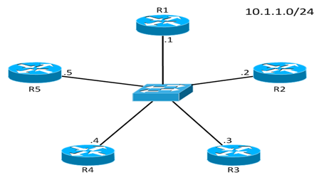
Topology

Configurations
R1
R1#conf t
Enter configuration commands, one per line. End with CNTL/Z.
R1(config)#interface loopback 0 [Dummy interface to test the directly connected network ]
R1(config-if)#ip address 10.10.20.1 255.255.255.0 [ip address of loopback interface]
R1(config-if)#no shut
R1(config-if)#keepalive 30 [trigger dummy interface after every 30 sec]
R1(config-if)#exit [exit from dummy interface]
R1(config)#interface fastEthernet 0/0
R1(config-if)#ip address 192.168.0.2 255.255.255.0 [ip address of fastEthernet 0/0]
R1(config-if)#no shut
R1(config-if)#exit
R1(config)#router ospf 1 [ie. ospf version 1]
R1(config-router)#router-id 10.2.2.2 [router id to select DR or BDR]
R1(config-router)#network 10.10.20.0 0.0.0.255 area 0 [network id of router to advertise]
R1(config-router)#network 192.168.0.0 0.0.0.255 area 0 [ip of directly connected network to dummy interface (to advertise)]
R1(config-router)#exit
R1(config)#hostname R1
R1(config)#exit
R1#wr
Building configuration…
[OK]
R1#sh run [Below this you will get output]
[R1 output after configuring all the routers]
R1#sh ip route
Codes: C – connected, S – static, R – RIP, M – mobile, B – BGP
D – EIGRP, EX – EIGRP external, O – OSPF, IA – OSPF inter area
N1 – OSPF NSSA external type 1, N2 – OSPF NSSA external type 2
E1 – OSPF external type 1, E2 – OSPF external type 2
i – IS-IS, su – IS-IS summary, L1 – IS-IS level-1, L2 – IS-IS level-2
ia – IS-IS inter area, * – candidate default, U – per-user static route
o – ODR, P – periodic downloaded static route
Gateway of last resort is not set
172.16.0.0/30 is subnetted, 1 subnets
O 172.16.0.0 [110/74] via 192.168.0.3, 00:12:39, FastEthernet0/0
10.0.0.0/8 is variably subnetted, 4 subnets, 2 masks
O 10.10.10.1/32 [110/11] via 192.168.0.1, 00:12:39, FastEthernet0/0
C 10.10.20.0/24 is directly connected, Loopback0
O 10.10.30.1/32 [110/11] via 192.168.0.3, 00:12:39, FastEthernet0/0
O 10.10.40.1/32 [110/75] via 192.168.0.3, 00:12:39, FastEthernet0/0
C 192.168.0.0/24 is directly connected, FastEthernet0/0
R1#ping 10.10.10.1
Type escape sequence to abort.
Sending 5, 100-byte ICMP Echos to 10.10.10.1, timeout is 2 seconds:
!!!!!
Success rate is 100 percent (5/5), round-trip min/avg/max = 36/85/188 ms
R1#
R2
R2(config)#interface loopback 0
R2(config-if)#ip address 10.10.10.1 255.255.255.0
R2(config-if)#no shut
R2(config-if)#keepalive 30
R2(config-if)#exit
R2(config)#interface fastEthernet 0/0
R2(config-if)#ip address 192.168.0.1 255.255.255.0
R2(config-if)#no shut
R2(config-if)#exit
R2(config)#router ospf 1
R2(config-router)#router-id 10.1.1.1
R2(config-router)#network 10.10.10.0 0.0.0.255 area 0
R2(config-router)#network 192.168.0.0 0.0.0.255 area 0
R2(config-router)#exit
R2(config)#^Z
R2#wr
Building configuration…
R2#sh ip route
Codes: C – connected, S – static, R – RIP, M – mobile, B – BGP
D – EIGRP, EX – EIGRP external, O – OSPF, IA – OSPF inter area
N1 – OSPF NSSA external type 1, N2 – OSPF NSSA external type 2
E1 – OSPF external type 1, E2 – OSPF external type 2
i – IS-IS, su – IS-IS summary, L1 – IS-IS level-1, L2 – IS-IS level-2
ia – IS-IS inter area, * – candidate default, U – per-user static route
o – ODR, P – periodic downloaded static route
Gateway of last resort is not set
172.16.0.0/30 is subnetted, 1 subnets
O 172.16.0.0 [110/74] via 192.168.0.3, 00:13:02, FastEthernet0/0
10.0.0.0/8 is variably subnetted, 4 subnets, 2 masks
C 10.10.10.0/24 is directly connected, Loopback0
O 10.10.20.1/32 [110/11] via 192.168.0.2, 00:13:02, FastEthernet0/0
O 10.10.30.1/32 [110/11] via 192.168.0.3, 00:13:02, FastEthernet0/0
O 10.10.40.1/32 [110/75] via 192.168.0.3, 00:13:02, FastEthernet0/0
C 192.168.0.0/24 is directly connected, FastEthernet0/0
R2#ping 10.10.20.1
Type escape sequence to abort.
Sending 5, 100-byte ICMP Echos to 10.10.20.1, timeout is 2 seconds:
!!!!!
Success rate is 100 percent (5/5), round-trip min/avg/max = 56/82/128 ms
R2#
R3
R3(config)#interface loopback 0
R3(config-if)#ip address 10.10.30.1 255.255.255.0
R3(config-if)#no shut
R3(config-if)#keepalive 30
R3(config-if)#exit
R3(config)#interface FastEthernet0/0
R3(config-if)#ip address 192.168.0.3 255.255.255.0
R3(config-if)#no shut
R3(config-if)#exit
R3(config)#interface Serial0/0
R3(config-if)#ip address 172.16.0.1 255.255.255.252
R3(config-if)#no shut
R3(config-if)#keepalive 30
R3(config-if)#exit
R3(config)#router ospf 1
R3(config-router)#router-id 10.3.3.3
R3(config-router)#network 10.10.30.0 0.0.0.255 area 0
R3(config-router)#network 172.16.0.0 0.0.0.3 area 0
R3(config-router)#network 192.168.0.0 0.0.0.255 area 0
R3(config-router)#^Z
R3(config)#^Z
R3#wr
Building configuration…
R3#sh ip route
Codes: C – connected, S – static, R – RIP, M – mobile, B – BGP
D – EIGRP, EX – EIGRP external, O – OSPF, IA – OSPF inter area
N1 – OSPF NSSA external type 1, N2 – OSPF NSSA external type 2
E1 – OSPF external type 1, E2 – OSPF external type 2
i – IS-IS, su – IS-IS summary, L1 – IS-IS level-1, L2 – IS-IS level-2
ia – IS-IS inter area, * – candidate default, U – per-user static route
o – ODR, P – periodic downloaded static route
Gateway of last resort is not set
172.16.0.0/30 is subnetted, 1 subnets
C 172.16.0.0 is directly connected, Serial0/0
10.0.0.0/8 is variably subnetted, 4 subnets, 2 masks
O 10.10.10.1/32 [110/11] via 192.168.0.1, 00:13:31, FastEthernet0/0
O 10.10.20.1/32 [110/11] via 192.168.0.2, 00:13:31, FastEthernet0/0
C 10.10.30.0/24 is directly connected, Loopback0
O 10.10.40.1/32 [110/65] via 172.16.0.2, 00:13:31, Serial0/0
C 192.168.0.0/24 is directly connected, FastEthernet0/0
R3#ping 10.10.10.1
Type escape sequence to abort.
Sending 5, 100-byte ICMP Echos to 10.10.10.1, timeout is 2 seconds:
!!!!!
Success rate is 100 percent (5/5), round-trip min/avg/max = 44/87/188 ms
R3#
R4
R4(config)#interface loopback 0
R4(config-if)#ip address 10.10.40.1 255.255.255.0
R4(config-if)#no shut
R4(config-if)#keepalive 30
R4(config-if)#exit
R4(config)#interface serial 0/0
R4(config-if)#ip address 172.16.0.2 255.255.255.252
R4(config-if)#no shut
R4(config-if)#exit
R4(config)#router ospf 1
R4(config-router)#router-id 10.4.4.4
R4(config-router)#network 10.10.40.0 0.0.0.255 area 0
R4(config-router)#network 172.16.0.0 0.0.0.3 area 0
R4(config-router)#exit
R4(config)#^Z
R4#wr
Building configuration…
R4#sh ip route
Codes: C – connected, S – static, R – RIP, M – mobile, B – BGP
D – EIGRP, EX – EIGRP external, O – OSPF, IA – OSPF inter area
N1 – OSPF NSSA external type 1, N2 – OSPF NSSA external type 2
E1 – OSPF external type 1, E2 – OSPF external type 2
i – IS-IS, su – IS-IS summary, L1 – IS-IS level-1, L2 – IS-IS level-2
ia – IS-IS inter area, * – candidate default, U – per-user static route
o – ODR, P – periodic downloaded static route
Gateway of last resort is not set
172.16.0.0/30 is subnetted, 1 subnets
C 172.16.0.0 is directly connected, Serial0/0
10.0.0.0/8 is variably subnetted, 4 subnets, 2 masks
O 10.10.10.1/32 [110/75] via 172.16.0.1, 00:00:52, Serial0/0
O 10.10.20.1/32 [110/75] via 172.16.0.1, 00:00:52, Serial0/0
O 10.10.30.1/32 [110/65] via 172.16.0.1, 00:00:52, Serial0/0
C 10.10.40.0/24 is directly connected, Loopback0
O 192.168.0.0/24 [110/74] via 172.16.0.1, 00:00:52, Serial0/0
R4#ping 10.10.30.1
Type escape sequence to abort.
Sending 5, 100-byte ICMP Echos to 10.10.30.1, timeout is 2 seconds:
!!!!!
Success rate is 100 percent (5/5), round-trip min/avg/max = 20/67/144 ms
sR4#